- 您现在的位置:买卖IC网 > Sheet目录3850 > AT89C51CC03C-S3SIM (Atmel)IC 8051 MCU FLASH 64K 52PLCC
131
AT89C51CC03
4182O–CAN–09/08
Functional Description
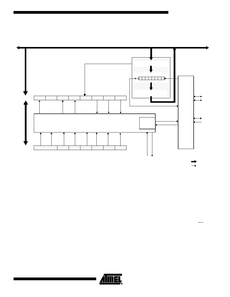
Figure 58 shows a detailed structure of the SPI Module.
Figure 58. SPI Module Block Diagram
Operating Modes
The Serial Peripheral Interface can be configured in one of the two modes: Master mode
or Slave mode. The configuration and initialization of the SPI Module is made through
two registers:
The Serial Peripheral Control register (SPCON)
The Serial Peripheral Status and Control Register (SPSCR)
Once the SPI is configured, the data exchange is made using:
The Serial Peripheral DATa register (SPDAT)
During an SPI transmission, data is simultaneously transmitted (shifted out serially) and
received (shifted in serially). A serial clock line (SCK) synchronizes shifting and sam-
pling on the two serial data lines (MOSI and MISO). A Slave Select line (SS) allows
individual selection of a Slave SPI device; Slave devices that are not selected do not
interfere with SPI bus activities.
Shift Register
0
1
2
3
4
5
6
7
Internal Bus
Pin
Control
Logic
MISO
MOSI
SCK
M
S
Clock
Logic
SPI Interrupt
8-bit bus
1-bit signal
SS
FCLK
Receive Data Register
SPDAT
SPI
Control
Transmit Data Register
-MODF
SPIF
OVR
SPTE
UARTM SPTEIE MODFIE
SPSCR
SPEN
MSTR
SPR2
SSDIS
CPOL
CPHA
SPR1
SPR0
SPCON
Request
PERIPH
发布紧急采购,3分钟左右您将得到回复。
相关PDF资料
AT89C51CC03C-RLTIM
IC 8051 MCU FLASH 64K 44VQFP
AT89C51CC03C-7CTIM
IC 8051 MCU FLASH 64K 64BGA
AT89C5132-ROTIL
IC 8051 MCU FLASH 64K USB 80TQFP
PIC18F46K80-I/P
MCU PIC 64KB FLASH 40DIP
AT89C5131A-RDTIL
IC 8051 MCU FLASH 32K USB 64VQFP
PIC24EP64GP202-I/SP
MCU 16BIT 64KB FLASH 28SPDIP
PIC24EP64MC202-I/SP
MCU 16BIT 64KB FLASH 28SPDIP
PIC18LF26J53-I/SP
IC PIC MCU 64KB FLASH 28SPDIP
相关代理商/技术参数
AT89C51CC03C-SLRIM
功能描述:IC 8051 MCU FLASH 64K 44PLCC RoHS:否 类别:集成电路 (IC) >> 嵌入式 - 微控制器, 系列:AT89C CAN 标准包装:1,500 系列:AVR® ATtiny 核心处理器:AVR 芯体尺寸:8-位 速度:16MHz 连通性:I²C,LIN,SPI,UART/USART,USI 外围设备:欠压检测/复位,POR,PWM,温度传感器,WDT 输入/输出数:16 程序存储器容量:8KB(4K x 16) 程序存储器类型:闪存 EEPROM 大小:512 x 8 RAM 容量:512 x 8 电压 - 电源 (Vcc/Vdd):2.7 V ~ 5.5 V 数据转换器:A/D 11x10b 振荡器型:内部 工作温度:-40°C ~ 125°C 封装/外壳:20-SOIC(0.295",7.50mm 宽) 包装:带卷 (TR)
AT89C51CC03C-SLSIM
制造商:ATMEL 制造商全称:ATMEL Corporation 功能描述:Enhanced 8-bit MCU with CAN Controller and Flash Memory
AT89C51CC03U-7CTIM
功能描述:IC 8051 MCU FLASH 64K 64BGA RoHS:否 类别:集成电路 (IC) >> 嵌入式 - 微控制器, 系列:AT89C CAN 标准包装:9 系列:87C 核心处理器:8051 芯体尺寸:8-位 速度:40/20MHz 连通性:UART/USART 外围设备:POR,WDT 输入/输出数:32 程序存储器容量:32KB(32K x 8) 程序存储器类型:OTP EEPROM 大小:- RAM 容量:256 x 8 电压 - 电源 (Vcc/Vdd):4.5 V ~ 5.5 V 数据转换器:- 振荡器型:内部 工作温度:0°C ~ 70°C 封装/外壳:40-DIP(0.600",15.24mm) 包装:管件
AT89C51CC03UA-7CTUM
制造商:Rochester Electronics LLC 功能描述: 制造商:Atmel Corporation 功能描述:
AT89C51CC03UA-RDTUM
功能描述:8位微控制器 -MCU CAN C51 64K FLASH UAR BOOT RoHS:否 制造商:Silicon Labs 核心:8051 处理器系列:C8051F39x 数据总线宽度:8 bit 最大时钟频率:50 MHz 程序存储器大小:16 KB 数据 RAM 大小:1 KB 片上 ADC:Yes 工作电源电压:1.8 V to 3.6 V 工作温度范围:- 40 C to + 105 C 封装 / 箱体:QFN-20 安装风格:SMD/SMT
AT89C51CC03UA-RDTZM
制造商:ATMEL 制造商全称:ATMEL Corporation 功能描述:Enhanced 8-bit MCU with CAN Controller and Flash Memory
AT89C51CC03UA-RLTUM
功能描述:8位微控制器 -MCU CAN C51 64K FLASH UAR BOOT RoHS:否 制造商:Silicon Labs 核心:8051 处理器系列:C8051F39x 数据总线宽度:8 bit 最大时钟频率:50 MHz 程序存储器大小:16 KB 数据 RAM 大小:1 KB 片上 ADC:Yes 工作电源电压:1.8 V to 3.6 V 工作温度范围:- 40 C to + 105 C 封装 / 箱体:QFN-20 安装风格:SMD/SMT
AT89C51CC03UA-RLTZM
制造商:ATMEL 制造商全称:ATMEL Corporation 功能描述:Enhanced 8-bit MCU with CAN Controller and Flash Memory